Introducing the Enhanced Rockfon® Chicago Metallic® Drywall Grid
Performance Properties:
- Heavy duty acoustical grid design features (660/670) stab-end.
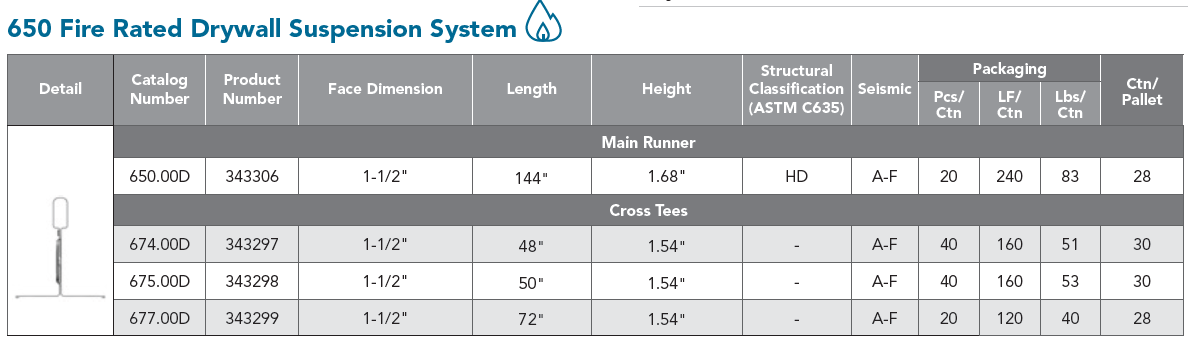
- Fire rated suspension system components are designed with expansion reliefs, making it suitable for fire-rated ceiling assemblies
- Eliminates the need for traditional framing and reduces onsite labor
- Sustainable: Minimum 25% recycled content, 100% locally recyclable
- Chicago Metallic® suspension systems meet a Class-A flame spread rating in accordance with ASTM standard E1264-08
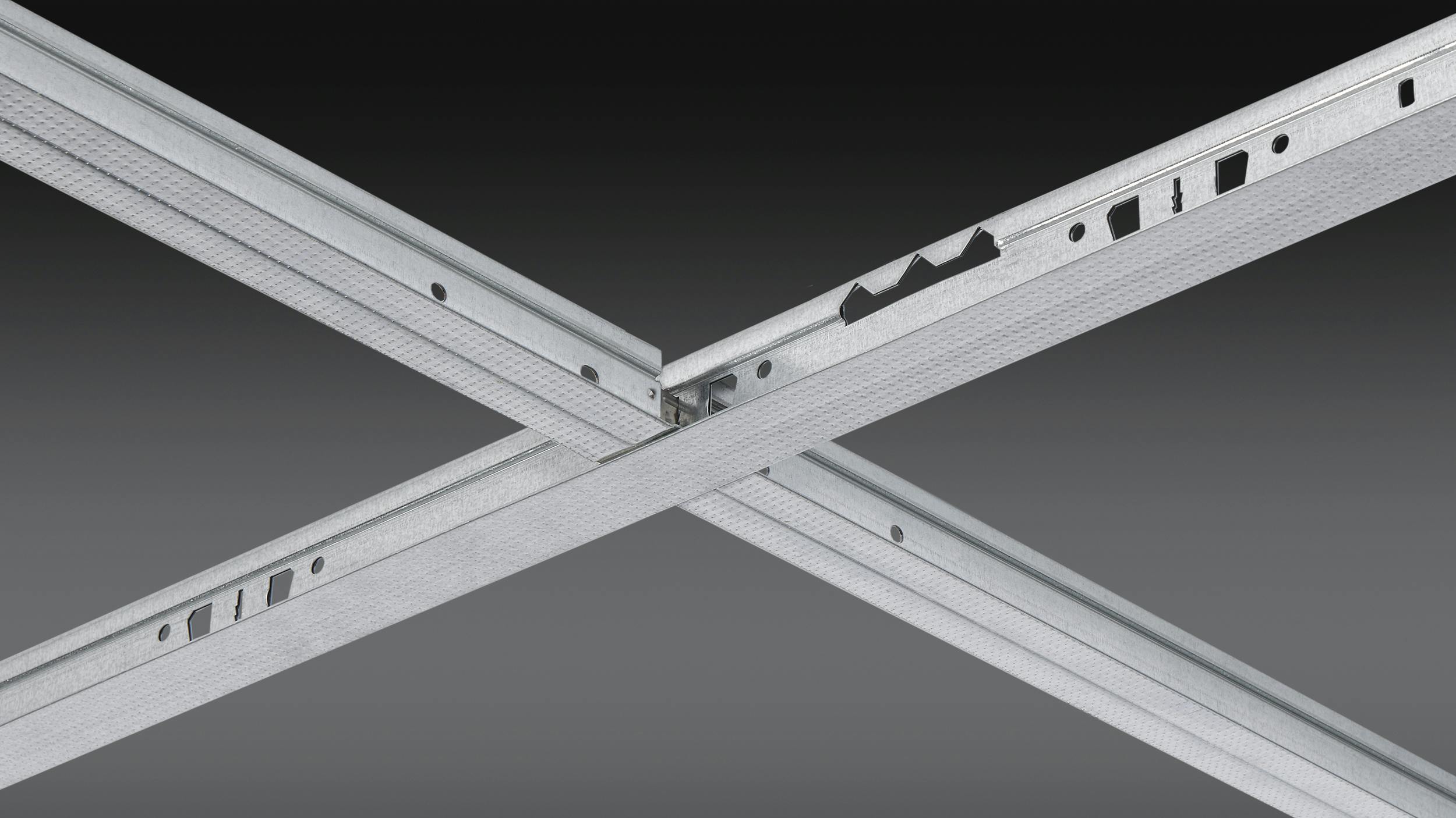
New and improved features include:
- Patented screw stop with wider knurled face
- Prevents screw spin out
- Wider 1½” face from previous version for easier screw installation
- Increased knurled facing
- Improves screw grab for faster, more efficient installation
- Additional slotting
- Group slotting used for Main Runners and Cross Tees supports Type G and Type F light fixture compatibility
- Standard cross tee sizes of 4’, 6’, and 50”
- Increased strength and torsional rigidity
- New double-stitched web
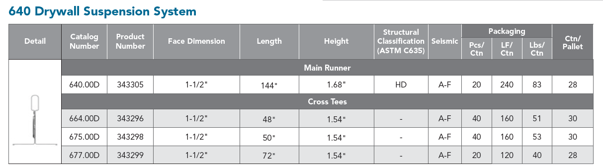
- Increased profile heights – up to 1.68”
- New bulb design
- Reduced main runner fire breaks
- One fire break per main from previous three – reduces hanger wire installation
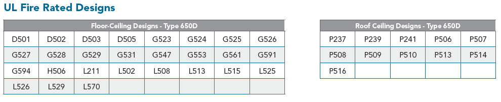
- Featured in 7 new fire-rated UL assemblies and 38 total fire-rated UL assemblies
- Manufactured with G40 steel for durability, and backed by a 40-year warranty
- G90 steel available for exterior applications