Chicago Metallic® 200 Hook-Grid™ 15/16" and 250 Hook-Grid™ Fire-Rated 15/16" grid ceiling system is available in intermediate and heavy-duty designs, non-fire rated and fire rated construction, and is built with HDG 30 steel. This drop ceiling grid features demountable hook-end cross tees for a quick and easily assembly. Chicago Metallic™ Grid Systems are third party certified to meet ASTM standards.
Performance Properties:
- Intermediate and heavy duty designs are available, along with hook-end cross tees
- Fire rated grid components are designed with expansion reliefs, making it suitable for fire-rated ceiling assemblies
- Available in (200) non-fire rated, and (250/270) fire rated
- Sustainable: Minimum 25% recycled content, 100% locally recyclable
- Chicago Metallic® suspension systems meet a Class-A flame spread rating in accordance with ASTM standard E1264-08
Available in the following standard colors, Rockfon® Color-all™ colors, and RAL color options.
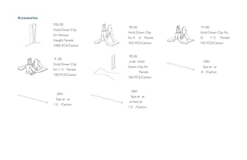
For packaging information, please download datasheet.